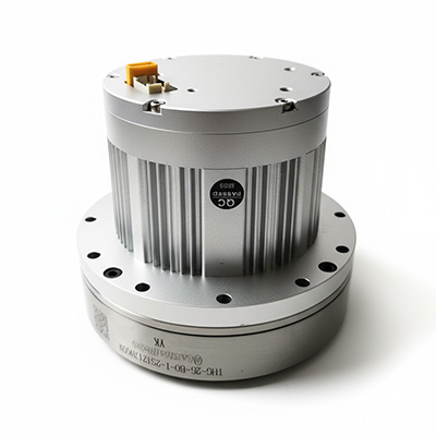
All-in-one robotic joint actuator
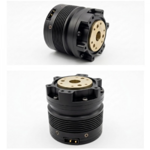
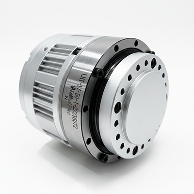
The 60AIM-JM Series represents a cutting-edge line of integrated frameless/short servo motors combining multi-stage direct drive (DD) motor structures with advanced control electronics. By integrating the servo driver directly onto the motor, the 60AIM-JM series simplifies wiring systems, maximizes spatial efficiency, and minimizes tracking lag, making it an ideal choice for high-precision, space-constrained robotic and automation environments.
Core Product Features
Battery-Free Mechanical Multi-Turn Absolute Encoder: Features a highly reliable 15-bit single-turn and 800-turn (±400 turns) multi-turn absolute mechanical encoder architecture that retains position data without requiring battery backup (Single-turn or multi-turn versions are optional).
High Torque & Ultra-Compact Footprint: Engineered with a multi-stage DD motor structure for maximum torque output, packaged in a highly integrated design that significantly reduces overall volume and simplifies system wiring.
FOC Vector Control: Delivers true fully closed-loop control across Position, Speed, and Current loops.
Zero-Hysteresis Homing: Capable of operating in an absolute pulse status immediately following the homing routine, completely eliminating tracking lag.
Flexible Operating Modes: Equipped with a 16-bit electronic gear function and supports multiple control methods:
Position Mode: Driven via communication control, Pulse + Direction, or Orthogonal Phase pulse signals.
Speed Mode: Driven via communication control or PWM control.
Torque Mode: Driven via communication control or PWM control.
Industrial Grade Safety & Communication: Fully guarded with built-in software/hardware over-current, over-voltage, and over-temperature protections. Supports scalable industrial fieldbus networks through selectable CANopen or Modbus-RTU (RS485) communication protocols.
Global Control & Signal Performance
(Shared across all JM17 and JM25 models)
Max Input Pulse Frequency: 500 kHz
Pulse Commands Supported: Pulse + Direction, A/B Phase Orthogonal signals
Electronic Gear Ratio Range: Ten to the negative third power, Ratio, Ten to the third power
Position Feedback Resolution: 32,768 steps per revolution
Interface & Wiring Pinout Definitions
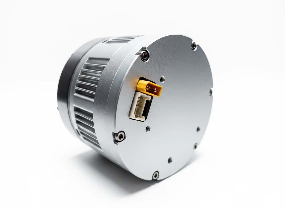
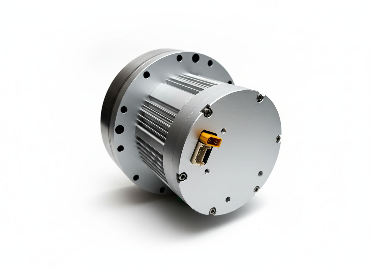
Both motor variations share an identical architectural block for their electrical connectivity interfaces, split between a high-power input plug and an isolated 10-pin signal/bus housing.
1. Main Power Interface
Pin 1 (+V): DC Power Input Positive (+24V to +48VDC). Warning: Reverse polarity configuration will critically damage the internal driver boards.
Pin 2 (GND): DC Power Input Negative (Ground). Note: Ensure secure frame grounding; do not loop with primary main circuit breakers.
2. Communication & Command I/O Ports (10-Pin Layout)
Pin 1 (CANL): CAN-low differential line (built-in 120Ω termination line).
Pin 2 (CANH / 485B): CAN-high differential line. Bridging Pin 1 and Pin 2 together engages the local termination resistor. Functions as 485B on Modbus variants.
Pin 3 (CANH / 485A): Alternate CAN-high output node. Functions as 485A on Modbus variants.
Pin 4 (CANM): Common reference ground for isolated CAN bus communication lines.
Pin 5 (VCC / NC): Auxiliary power output (JM17) / No Connection (JM25).
Pin 6 (GDM): Ground reference node for logic lines and shielding layers
Pin 7 (PU-): Pulse/Direction negative input terminal. Internal current limits native to 3.3V–5V signals; external resistors are required for higher signal voltages.
Pin 8 (PU): Direction or A/B Quadrature pulse positive input terminal. Minimum pulse width threshold >1.2us. Supports 5V–24V levels natively.
Pin 9 (DIR+): Pulse/Direction positive input terminal or differential forward signal node.
Pin 10 (DIR): Direction or A/B Quadrature phase negative input terminal. Internal current limits native to 3.3V–5V signals; external resistors are required for higher signal voltages.