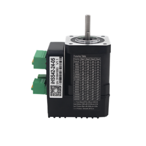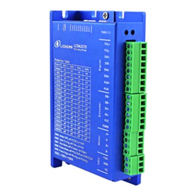
Two Phase Closed-loop Stepper Motor Driver
It's used to control NEMA17 and NEMA23 closed-loop stepper motor
1. Voltage input range: DC: 20V ~ 50V (recommended 36V or more)
2. Maximum peak current: 6A
3. Subdivision range: 400 ~ 51200ppr
4. Pulse form: pulse + direction, CW / CCW
5. Impulse response frequency: 0 ~ 200kHz
6. Logic input current: 10 ~ 20mA
7. Power-on parameter auto-tuning function
8. Closed-loop vector control to ensure that the motor high-speed high-torque output, while ensuring that the motor does not lose step
9. With over-voltage, over-current, tracking error tolerance and other protection functions
Main parameters:
Parameter | LCDA257S | |||
Minimum value | Typical value | Maximum value | unit | |
Max peak current | - | - | 6 | A |
Input power voltage | 20 | 36 | 50 | Vdc |
Logic input current | 7 | 10 | 20 | mA |
Pulse frequency | - | - | 200 | kHz |
Driver terminal description
1) Power terminal definition
Symbol | Name |
A+ | A-phase motor winding positive terminal |
A- | A phase motor winding negative terminal |
B+ | B-phase motor winding positive terminal |
B- | B-phase motor winding negative terminal |
| +VDC | Power access positive terminal |
| GND | Power access ground |
2) Driver Encoder Terminal Definition:
| Symbol | Color | Explanation |
EB+ | Yellow | Motor encoder B phase positive input |
EB- | Green | Motor encoder B phase negative input |
EA+ | Black | Motor encoder A phase positive input |
EA- | Blue | Motor encoder A phase negative input |
VCC | Red | Encoder + 5V input |
EGND | White | Encoder power ground |
3) Control signal port
Name | Explanation |
PUL+ | Pulse input signal: pulse effective edge adjustable, the default pulse rising edge is valid; in order to reliably respond to the pulse signal, the pulse width should be greater than 1.2μs. Such as the use of +12 V or +24 V when the need to string 3K resistance |
PUL- | |
DIR+ | Direction input signal: high / low level signal, in order to ensure reliable reversing of the motor, the direction of the signal should be preceded by pulse signal at least 5μs to establish, such as the use of +12 V or +24 V string 3K resistor. |
DIR- | |
ENA+ | Enable control signal: This input signal is used to enable or disable. When ENA +, ENA- have input, the drive will cut off the motor phase to make the motor in a free state. When this function is not required, the terminal can be left floating. |
ENA- | |
Pend+ | Positioning completion signal positive side |
Pend- | Positioning completion signal negative |
ALM+ | Alarm output positive terminal |
ALM- | Alarm output negative terminal |
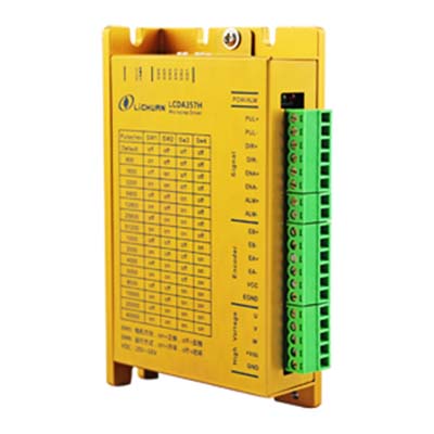
Three phase closed-loop stepper motor driver
1. Voltage input range: 18V ~ 50VDC
2. Maximum peak current: 7A
3. Subdivision range: 200 ~ 51200ppr
4. Signal input: differential / single-ended, pulse / direction
5. Impulse response limit frequency: 200KHZ
6. Power-on parameter auto-tuning function
7. Closed-loop vector control to ensure that the motor high-speed high-torque output, while ensuring that the motor does not lose step
8. With over-voltage, over-current, tracking error tolerance and other protection
Main parameters:
1. Electrical Specifications
Parameter | LCDA357H | |||
Minimum value | Typical value | Maximum value | unit | |
Max peak current | - | - | 7 | A |
Input power voltage | 20 | 36 | 50 | Vdc |
Logic input current | 7 | 10 | 16 | mA |
Pulse frequency | - | - | 200 | kHz |
2.Interface definition
1) Motor & power input port
Symbol | Name | Explanation |
U- | Motor U phase winding | |
V | Motor V phase winding | |
W | Motor W phase winding | |
Vdc | Input DC power supply positive | +20V~+50V |
| GND | Input power ground | 0V |
2) Encoder signal input port:
Symbol | Name |
EB+ | Motor encoder B phase positive input |
EB- | Motor encoder B phase negative input |
EA+ | Motor encoder A positive input |
EA- | Motor encoder A phase negative input |
VCC | Encoder power supply |
EGND | Encoder power ground |
3) Control signal port:
Name | Explanation |
PUL+ | Pulse input signal: pulse effective edge adjustable, the default pulse rising edge is valid; in order to reliably respond to the pulse signal, the pulse width should be greater than 1.2μs. Such as the use of +12 V or +24 V when the need to string 3K resistance |
PUL- | |
DIR+ | Direction input signal: high / low level signal, in order to ensure reliable reversing of the motor, the direction of the signal should be preceded by pulse signal at least 5μs to establish, such as the use of +12 V or +24 V string 3K resistor. |
DIR- | |
ENA+ | Enable control signal: This input signal is used to enable or disable. When ENA +, ENA- have input, the drive will cut off the motor phase to make the motor in a free state. When this function is not required, the terminal can be left floating. |
ENA- | |
Pend+ | Positioning completion signal positive side |
Pend- | Positioning completion signal negative |
ALM+ | Alarm output positive terminal |
ALM- | Alarm output negative terminal |