Engineering Cost Breakdown: How Pitch and Groove Depth Drive Reversing
Reversing Screw Pricing
Self-reversing screws—often called level-wind screws or reciprocating lead screws—are mechanical marvels. By routing a continuous bidirectional helical track with smooth turnaround loops at each end, they convert single-direction rotary motion into automatic, back-and-forth linear travel without reversing the motor.
When engineers transition from off-the-shelf standard screws (like standard 10 mm or 12 mm leads) to custom configurations (such as a 6 mm pitch over a 150 mm stroke), quotation totals can jump significantly.
Unlike standard lead screws formed by high-speed thread rolling, self-reversing screws require precision multi-axis CNC milling or grinding. Two primary dimensional parameters dictate the bulk of CNC cycle time, tooling wear, and part yield: pitch (lead) and groove depth.
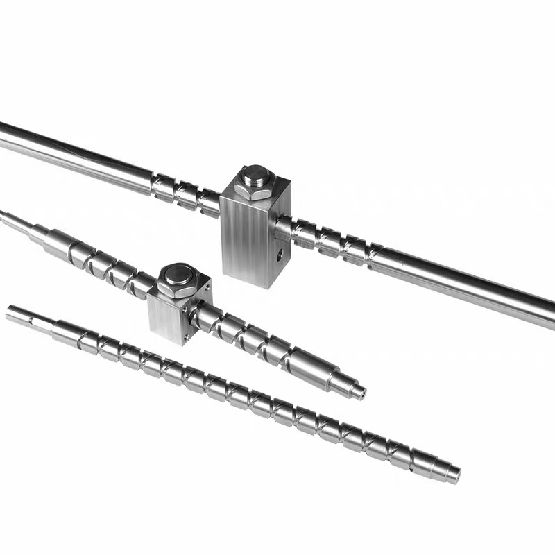
Pitch: More Cycles Mean an Exponentially Longer Toolpath
The pitch determines how far the carriage travels linearly per single revolution of the shaft. For a fixed stroke, smaller pitch means more cycles (turns), which directly inflates cycle time.
Number of Cycles(Turns)=Stroke Length/Pitch
Consider a 150 mm stroke:
10 mm pitch: Requires 15 cycles per stroke (150/10).
6 mm pitch: Requires 25 cycles per stroke (150/6).
Why This Impacts Pricing:
Total Cutting Distance: The cutting tool must traverse both forward and reverse tracks across the full shaft length. Dropping from a 10 mm to a 6 mm pitch increases the continuous helical path length by over 60%.
Intersection Milling: Reversing tracks cross each other at every cycle. Every crossover point requires precise spindle control, feed rate de-acceleration, and chip evacuation to prevent burrs or tool gouging. More cycles mean more intersection crossings per part.
CAM & Setup Overhead: Off-the-shelf pitches use pre-optimized CAM toolpaths and established fixtures. Custom pitches require dedicated CAD/CAM toolpath generation, simulation for turnaround clearance, and first-article testing.
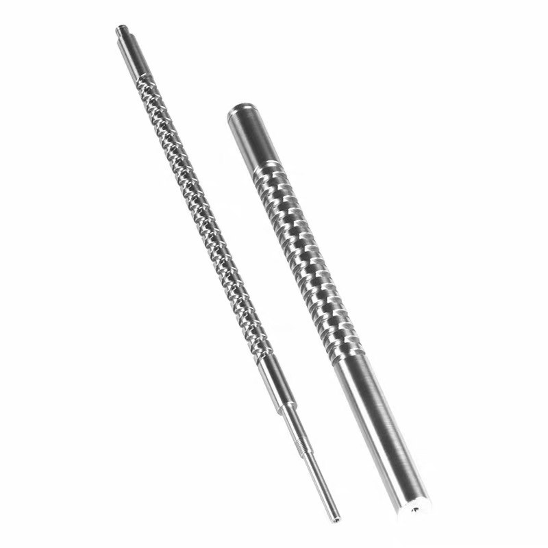
Groove Depth: Pass Count, Rigidity, and Breakage Risks
The depth of the slot guides the follower pawl (boat/crescent pin). While design intuition might suggest "deeper is safer to prevent the pawl from jumping out," cutting deeper channels in cylindrical tool steel introduces severe manufacturing challenges.
Multiple Pass Compounding
CNC end mills or custom form cutters cannot cut a deep, narrow groove in a single pass without snapping or binding.
A shallow groove (e.g., 0.5–1 mm deep) might only require 1 roughing pass and 1 finish pass.
A deep groove (e.g., 1.5–3 mm deep on smaller shaft diameters) often demands 3 to 5 step-down passes.
If a 6 mm pitch screw has 25 cycles and requires 4 depth passes instead of 2, the actual distance traveled by the cutter doubles across the entire run.
Tool Deflection and Tool Rigidity
Small-pitch tracks typically have narrow groove widths to fit the geometry. When the ratio of depth to width exceeds 2:1 or 3:1, tool deflection becomes a dominant failure mode:
Chatter and Surface Finish: Deep, slender cutters vibrate easily inside the groove, leaving chatter marks that ruin smooth travel for the follower pawl.
Feed Rate Penalties: To prevent chatter, feed speeds must be dropped by 40% to 60%, stretching cycle time further.
Tool Breakage Costs: If a micro-carbide tool snaps deep inside the turnaround curve on pass 4 of a 40-minute machining cycle, the entire blank is often scrapped. Scrap risk must be factored into production quotes.
Design Tips for Lowering Reversing Screw Costs
For projects requiring reciprocating linear motion on a budget, consider these design guidelines before finalizing drawings:
Leverage Gear Ratios Instead of Custom Pitches: If an application requires a net feed of 6 mm per drive rotation, consider pairing a standard, stock 10 mm reversing screw with a 1.67:1 gear or timing belt reduction. The savings on standard screw machining often outweigh the cost of a simple belt-and-pulley stage.
Limit Depth-to-Width Ratio: Keep the groove depth under 1.5x to 2x the groove width whenever possible. This preserves cutter rigidity, permits single- or two-pass roughing, and cuts cycle time significantly.
Specify Generous Turnaround Radii: Tight turnaround pockets at the stroke ends require small-diameter tools and slower feed rates. Providing the maximum permissible corner radius allows larger, stiffer cutting tools to run at higher speeds.
Standardize Shaft Diameters: Whenever possible, design around standard ground stock diameters (e.g., 12 mm, 16 mm, 20 mm, 25 mm). Custom pre-turned stock adds unnecessary material prep cost.
Recent post:
- Upgrade Your Automation: Lightweight Stepper Motorized Linear Actuators from RobotDigg
- Understanding Press Types: Pneumatic, Hydraulic, and Servo Drive Configurations
- Bridging the Hardware Gap: How Open-Source Motion Platforms Are Reshaping Simulation and Prototyping
- Engineering Cost Breakdown: How Pitch and Groove Depth Drive Reversing