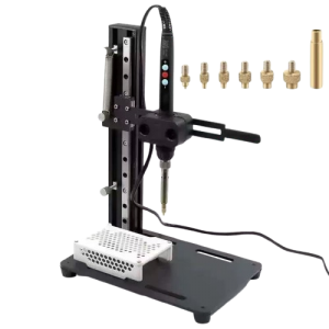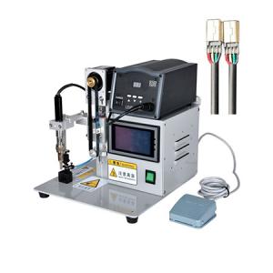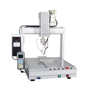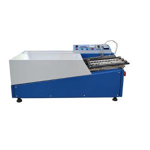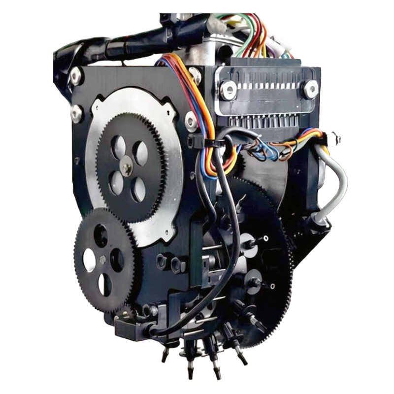
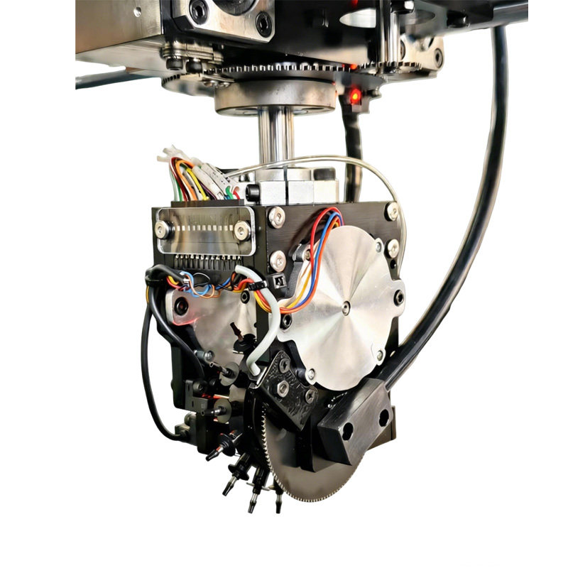
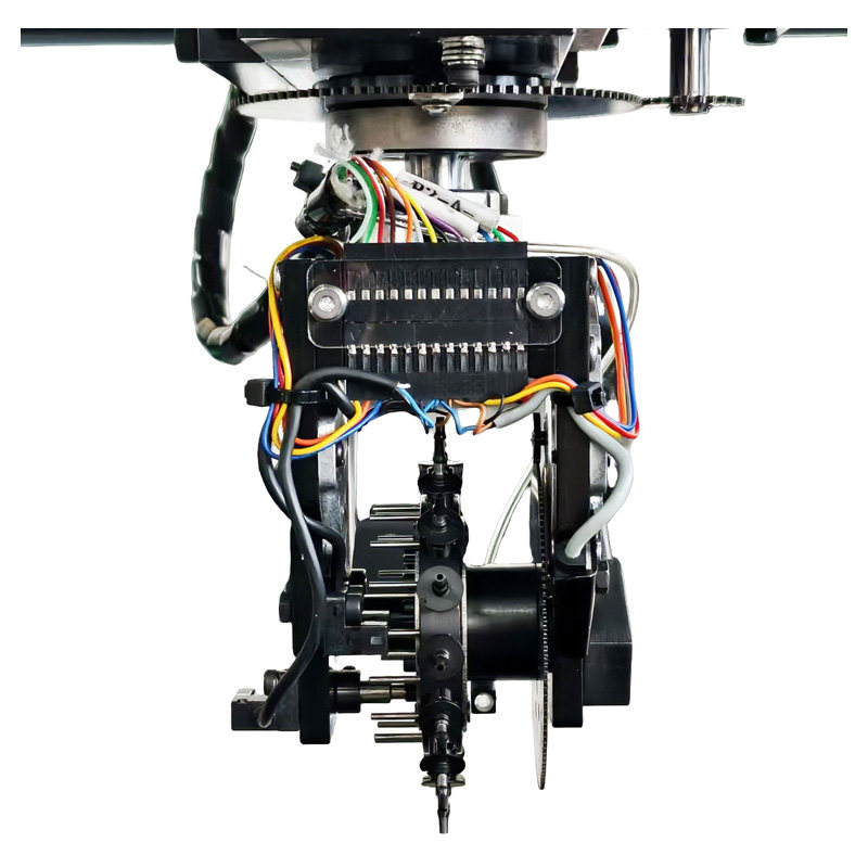
16-nozzle high speed Rotary Turret Placement Head
Note: Nozzles are Not included, it's separately available.
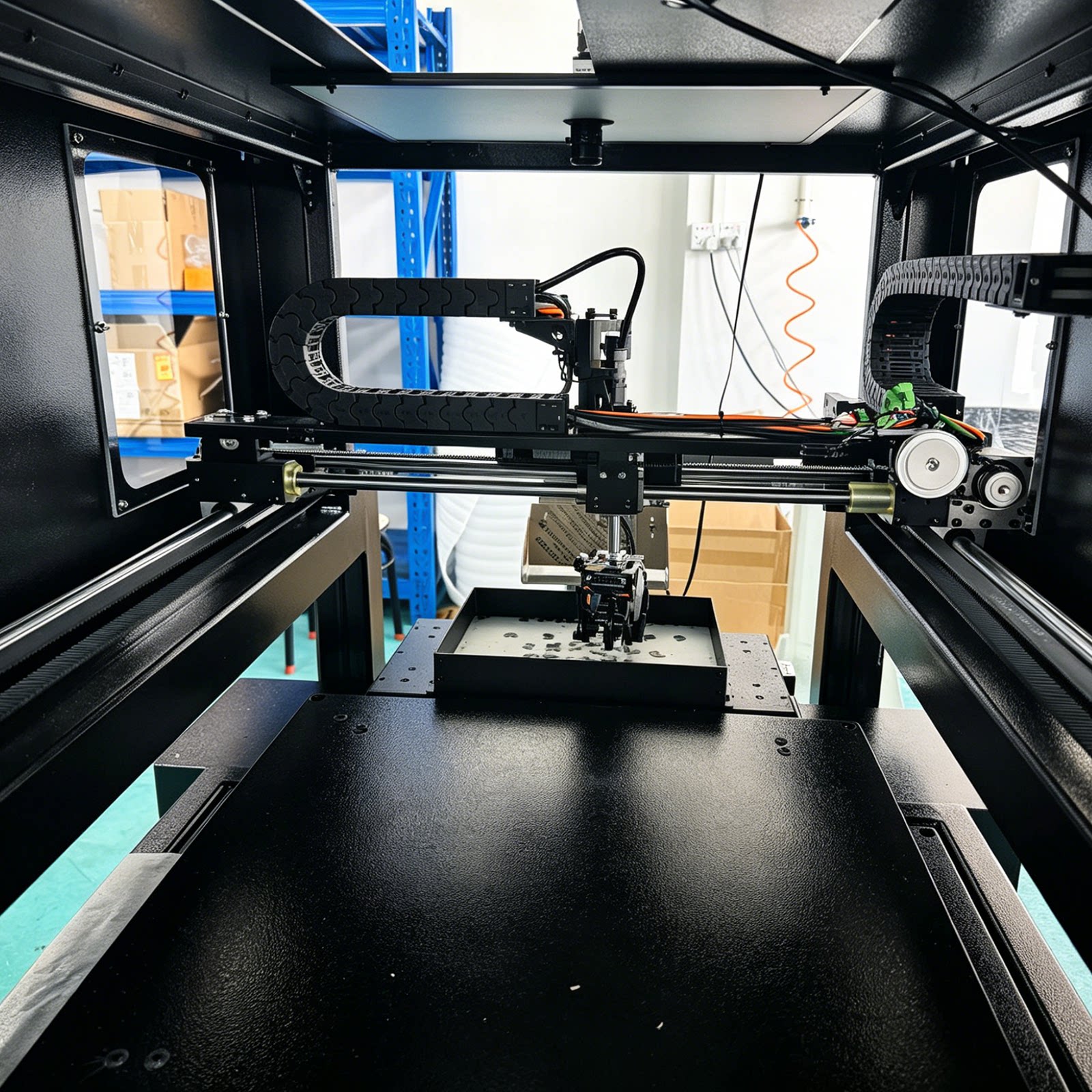
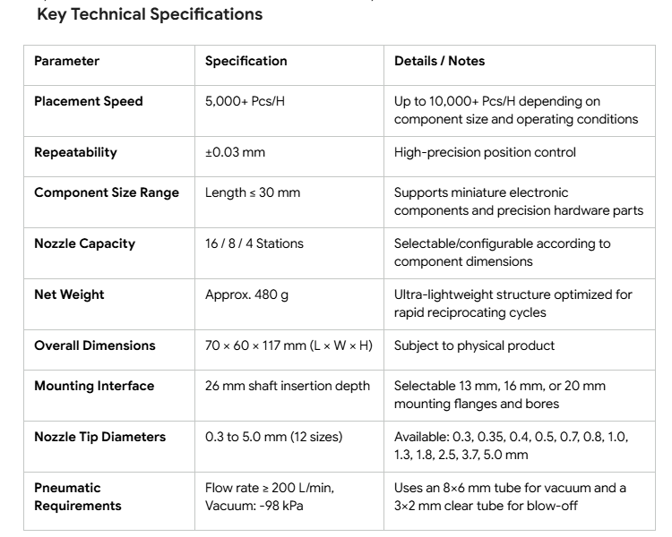
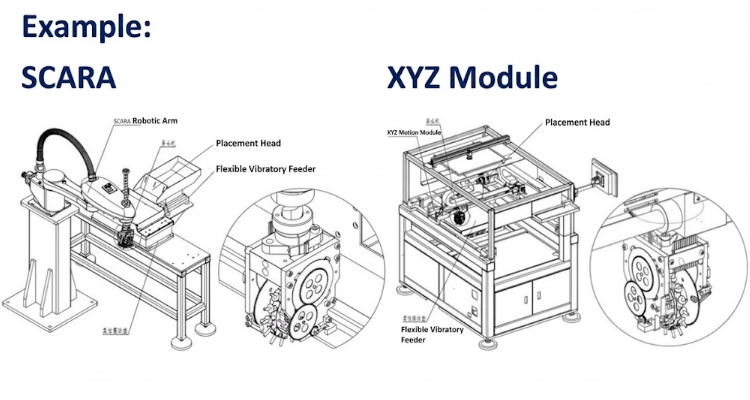
The Multi-Nozzle Rotary Turret Placement Head is an ultra-lightweight, compact end-effector engineered for surface mount technology (SMT), precision dispensing, and high-speed pick-and-place automated operations. Designed to reduce end-effector inertia on high-speed motion platforms, it seamlessly mounts to SCARA robot Z-axis ball screws or high-precision XY Cartesian gantry splines, and works in synchronization with flexible feeders and vibration feed systems.
Mechanical & Electrical Control
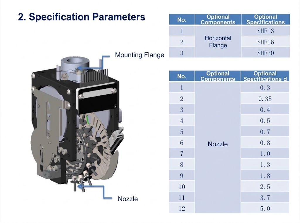
Turret Rotary Axis (R2):
Drive Settings: Gear ratio 1:7, driver microstepping set to 400, drive current set to 1.0–1.3 A.
Indexing Logic: Indexes 22.5° per nozzle station. Pulse equivalent must be set to 1 and displacement set to an exact integer of 175 pulses to eliminate cumulative float errors that cause nozzle misalignment.
Pick & Place Actuator Axis (R3):
Drive Settings: Gear ratio 4:1, driver microstepping set to 400, drive current set to 1.0–1.3 A.
3-Position Switching: Features a reciprocating selector pointer—clockwise 95° for vacuum pick, counterclockwise 95° for positive-pressure blow-off release, and horizontal center for home position (interrupter blocks photo sensor). Each cycle requires 26 reciprocating pulses and must return to home immediately.
Wiring & Electrical Interface:
Equipped with a 13-core flexible, torsion-resistant cable terminating in a 13-pin DuPont connector (covering stepper motor phases, 24V/0V power, and sensor signals).
Stepper motors are driven via 422 drivers; sensors are powered by 24V/0V and report to the motion control card inputs.
Optical Part Detection (Optional):
Supports an optional through-beam fiber-optic amplifier (transmitter and receiver) to verify part pickup status at the rotary station in real time.
Operating Logic & Homing Procedure
Mechanical Interlock: Turret rotation is strictly prohibited unless the pick/place actuator is confirmed at its horizontal home position, preventing mechanical collision or air valve binding.
Homing Sequence:
During system reset, the turret motor is disabled while the pick/place actuator axis homes first.
Once the pick/place axis reaches home, the turret motor is enabled.
The turret performs rapid coarse homing via proximity switch, followed by precision fine homing via a slotted optical switch to establish home offset (calibrated using a 2.49 mm pin gauge).
After homing, the system cycles all nozzles into the blow-off position to clear residual components.
Position Monitoring: Each nozzle station switch requires positive feedback from the in-position sensor; failure to detect triggers an alarm.
Maintenance & Handling Guidelines
Air Quality: Supply air (both vacuum and positive blow-off pressure) must remain clean, dry, and oil-free.
Nozzle Replacement: Uses a push-and-twist quick-release mechanism. After installation, gently pull the nozzle disk to verify positive seating and inspect internal spring return and O-ring positioning.
Cleaning Procedures: Never clean the main head assembly with liquid solvents. Nozzles must be detached prior to cleaning with alcohol, and thoroughly dried before reassembly.
Filter & Seal Maintenance:
The filter cotton in the switching valve center should be inspected and replaced bi-weekly depending on working conditions.
Switching valves and filter cotton may only be accessed by removing the right-side cover plate at the blow-off position.
Tighten M2.5 screws lightly—do not overtighten to prevent thread stripping.
For unused nozzle stations, 5.02×6 mm silicone plugs can be installed into the valve ports to maintain complete vacuum integrity.