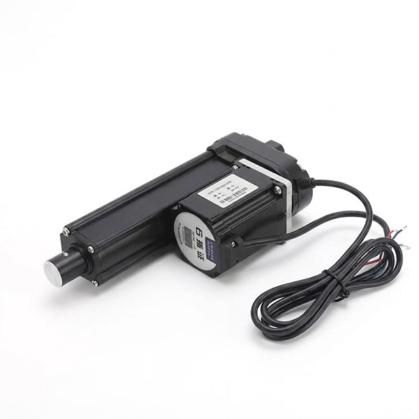
Stepper Motor Linear Actuator
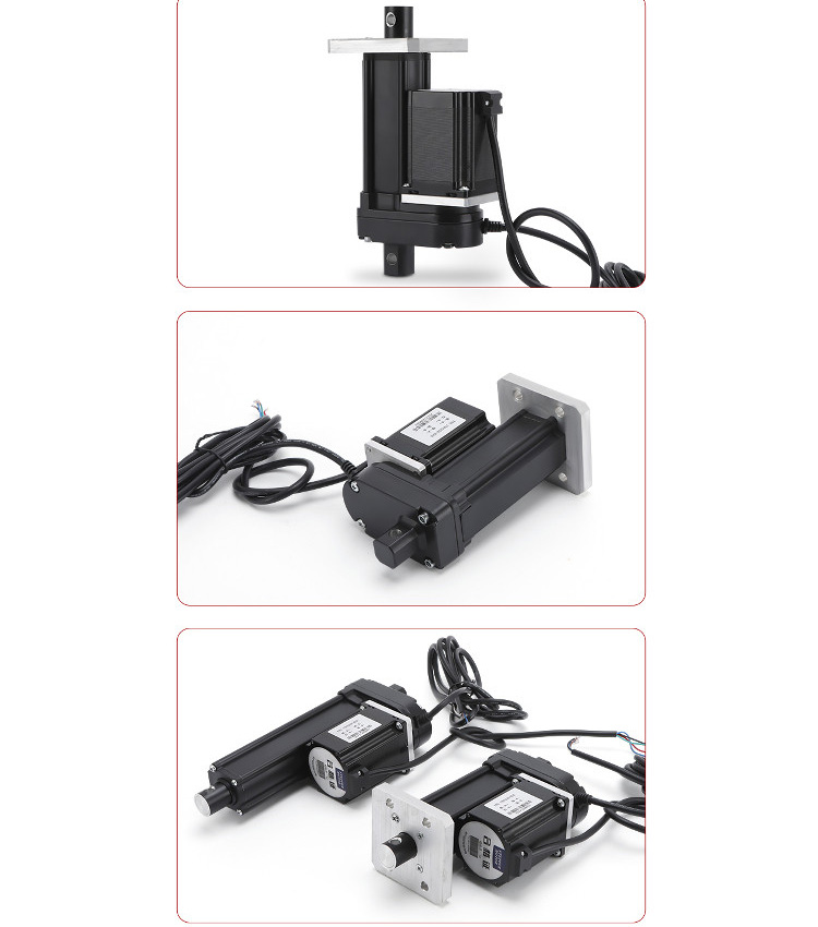
This NEMA 23 Stepper Motor Linear Actuator is built with high-strength metal construction designed for heavy-load, high-precision automation tasks. Featuring $360^\circ$ dustproof protection and a waterproof design, it provides superior durability in harsh industrial environments.
Linear Actuator Dimensions & Formulas
Motor Body Cross-Section: 56*56mm, Standard NEMA 23 frame
Total Length (L): L = 120mm + stroke
Main Body Length: 128.7mm
Front Shaft Extension: 27mm
Mounting Pin / Hole Dimensions: 8mm*2 holes, outer rod diameter 22mm, pin-to-edge distances specified as 42.07mm and 13.88mm.
Example Calculation (100 mm Stroke Actuator):
Fully Retracted Hole-to-Hole Distance: 220mm (120mm+100mm stroke)
Fully Extended Hole-to-Hole Distance: 320mm (120mm+100mm stroke+100mm travel)
Wiring & Pinout Tables
Left Table: Cable Pinout Definition
Pin 1–2: Limit Switches (Normally Open)
Pin 3: Motor Phase A+ — Black
Pin 4: Motor Phase A- — Green
Pin 5: Motor Phase B+ — Red
Pin 6: Motor Phase B- — Blue
Signal wires: Black (Extend 1), White (Extend 2), Blue (Retract 1), Brown (Retract 2)
Right Table: Driver Signal Interface Terminal Definition
Pin 1 (B-): Motor Phase B Negative Terminal (Motor B Phase Winding)
Pin 2 (B+): Motor Phase B Positive Terminal (Motor B Phase Winding)
Pin 3 (A-): Motor Phase A Negative Terminal (Motor A Phase Winding)
Pin 4 (A+): Motor Phase A Positive Terminal (Motor A Phase Winding)
Pin 5 (DC+): Power Input Positive (24-48V DC)
Pin 6 (GND): Power Input Ground
Note: Match wire colors to the corresponding driver terminals: Red (A+), Blue (A-), Green (B+), Black (B-). If wire colors do not match, contact technical support.